Ray Tracing Devlog 3 - Ray Tracing Math
2020-02-19 // 10 minutes- #c++
- //
- #ray-tracing
- //
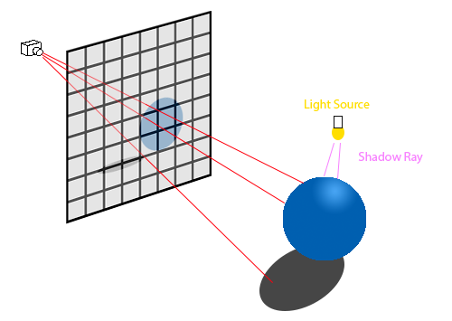
Ray tracing is a form of image-order rendering, where each pixel's final color is calculated independently by determining which objects impact the pixel and calculating from there. Put another way, one or more rays are shot through each x, y pixel in an image and the color is determined by what it hits and where that object sits relative to light sources.
There is also object-order rendering, where each object - instead of each pixel - is considered in order and then the algorithm determine which pixels they impact. You may see this type of rendering in OpenGL, Direct3D, and similar places. It's also commonly referred to as rasterization.
for each row in height
	for each column in width
		for each object in scene
			compute_viewing_ray();
			find_first_intersected();
			calculate_color();
for each object in scene
	for each row in influenced_height
		for each column in influenced_width
			compute_viewing_ray();
			find_first_intersected();
			calculate_color();
The pseuocode above illustrates the difference between image-order rendering and object-order rendering.
Ray Tracing Math
The basic ray tracing algorithm has three parts:
- Generating a ray based on the camera's origin and the pixel's midpoint.
- Calculating what objects the ray intersects with.
- Calculating the color of the pixel based off of the intersected object and light sources.
We're going to cover the the first step in this blog post. The vector math we'll discuss below will also be useful in future ray tracing discussions. Before discussing how to calculate the view ray, we should mention the difference between orthographic and perspective cameras. The perspective camera is akin to what you might recall from art class - where you draw multiple straight lines out from a single point to determine the "perspective" of your eye. The other common kind of camera - orthographic - has it's ray coming out from the camera from many points (one for each ray) and the rays are orthogonal to the image plane.
For the discussion in this post, we will be focusing solely on building a perspective camera.
p(t) = e + t(s - e)
In the above equation, we've defined a point p is calculated from camera point e to image point s. The amount of time spent on the ray is denoted as t - and t(0) is actually just e. Anything behind the camera will have a negative t. Lower (but positive) ts come in front of their larger positive counterparts. s - e is considered as the ray's direction. At this point, you might be wondering how we know the image point s ahead of time. That's the catch, we don't know s and we have to do a bit of math to figure that our for each viewing ray.
The first step to calculating s is establishing an orthonormal camera frame with the three basis vectors u, v, and w. Another way of thinking about the basis vectors is that it's an x, y, z coordinate system that happens to be aligned with e and the image plane. You may have noticed that the OBJ file we parsed last post doesn't have an image plane (or distance to the image plane) defined in it's spec. It's possible I've been misreading the spec, but let's discuss some alternatives in the meantime.
You could just add it to the file, but I don't recommend that as then your OBJ file is only usable by your parser. Instead, I recommend definining a static distance in your code. Later on, as our code gets more complex, we can consider moving that to a config file mapping or other options.
Once you have determined the image plane, you must iterate over each x,y pair in the plane (read: each pixel) and determine the ray's direction from the center of that pixel. As hinted at above, there are advanced sampling algorithms that shoot more than one ray per pixel. However, for the sake of introducing the mathematics, we will stick to one ray going through the center of the pixel. Now that the high level is covered, let's look more closely at the orthonormal camera frame comprised of u, v, and w.
(Brief aside: some of terms that we have to define in the code are defined in other file formats - such as the NFF file format that we will cover later. However, I wanted to start in the most bare bones manner possible. Moreover, OBJ is a popular file format whereas I only really see the NFF format used in academia. Lastly, many rendering systems end up defining their own custom internal representation, so I felt that start out with less would be a more appropriate jumping off point.)
w = from - e \\
normalize(w) \\
u = cross(up, w) \\
normalize(u) \\
v = cross(w, u) \\
normalize(v)
Notice how we normalized each vector? As discussed above, not doing that will cause errors in our math. Astute readers will notice two now terms - from and up. From is the center of your image plane, which you will need to define. You will also need to define which which up is. As silly as that sounds, there's actually a fair bit of disagreement on which direction counts as up. For the purposes of this blog series, we'll define the unit vector for up as (0, 1, 0).
fov = 90
radian = deg2rad(fov * 0.5)
hither = 1.0
left = hither * -tanf(radian)
right = hither * tanf(radian)
top = hither * tanf(radian)
bottom = hither * -tanf(radian)
Another term we'll need to define is the field of view. You can picture this as your cone of vision. Since peripheral vision requires additional math, we'll start by rendering only what you can see sharply in front of you. We can reasonably approximate this as 90 degrees to start out with. Hither is another way of denoting the distance of the image plane from the eye.
Next, we define left, right, top, and bottom as the edges of our image plane. Notice that I converted the 90 degrees to radians? Check to see what your languages library expects, but I did so in the pseudocode to call out that you will need to consider degrees vs radians depending on the math.
screen_width = 500
screen_height = 500
dist = get_length(from - e)

for j in 0 to screen_height
	for i in 0 to screen_width
		u_pos = ( left + (right - left) * (i * 0.5) ) / screen_width
		v_pos = ( top + (bottom - top) * (j * 0.5) ) / screen _height

		direction_vector = (w * dist * -1.0) + (u * u_pos) + (v * v_pos)

		// do stuff with ray
Hey! We're finally calculating the direction vector. I did say it would it would be a bit of math. Notice screen_width and screen_height? Yup, you'll need to define those as well. Before we work on optimization, multi-threading, etc. I recommend that you keep these two numbers small to keep the run times reasonable. Anywhere between 100 and 500 should be fine.
Hopefully the above math is easy enough to follow, but just to put it into words: for each i,j pair on the image plane we are determining how much the u and v (read: x and y) basis vector impact the ray direction.
Vector Math
Before we proceed to the code, we should also cover some of the math needed for a simple vector math library. We will need basic arithmetic operators (addition, subtraction, multiplication, and division) with the caveat that for addition and subtraction we will be operating on each scalar within the vector. We'll also need the length of a vector, be able to normalize the vector, calculate its dot product, and it's cross product. Let's go over the specific math needed for this and then we will dive into the code.
C = A + B \\
C_x = A_x + B_x \\
C_y = A_y + B_y \\
C_z = A_z + B_z
The above should be fairly straightforward, but by way of explanation: a new vector C is created by adding up the xs from A and B and likewise for y and z. This works the same way for subtraction, but we only need to cover the multiplication and division cases if the other operand is a scalar.
A_{length} = \sqrt{A_{x}^{2} + A_{y}^{2} + A_{z}^{2}}
The length of a 3D vector, or Euclidean norm if you prefer, can be thought of as an extension of the Pythagorean theorem. The main difference here is that we're accounting for one more dimension.
\widehat{A} = \dfrac{A}{A_{length}}
Getting the length is important for normalizing your vector into a unit vector as well (note: normal vector and unit vector mean the same thing). Remember those basis vectors we mentioned in the ray tracing math section? Well, that's just one of many uses for calculating a unit vector.
There's plenty of other useful vector math operations, however we'll wrap up by discussing dot and cross products.
dot = A • B \\
dot = A_x * B_x + A_y * B_y + A_z * B_z
Dot product is fairly straightforward, just multiply each component of a vector by it's partner in the other vector and then add them all up.
C = A \times B \\
C_x = (A_y * B_z) - (A_z * B_y) \\
C_y = (A_z * B_x) - (A_x * B_z) \\
C_z = (A_x * B_y) - (A_y * B_x)
Cross product is a little trickier, but if you follow the formula above (and write some nice unit tests to double check for typo based mistakes) you should be fine. Also note, it only exists in three and seven dimensions, if you want to know more check the generalizations section of the cross product page.
So why do we need the cross product and dot product? The cross product is handy because it returns a vector that is orthogonal to both of it's input vectors - which is pretty handy when we need an orthonormal camera frame to make this all work. The dot product is useful in determining angles between vectors. This will be useful later when we calculate how light bounces off of surfaces, but is also handy for soh cah toa calculations.
-
// rust code -
// cpp code